
Interface geometry
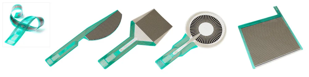
Flat, curved, narrow, annular or interrupted contact areas require different active layouts.
Choose the array around the contact geometry and measurement objective. The selected array is then matched with compatible acquisition hardware and analysis software.
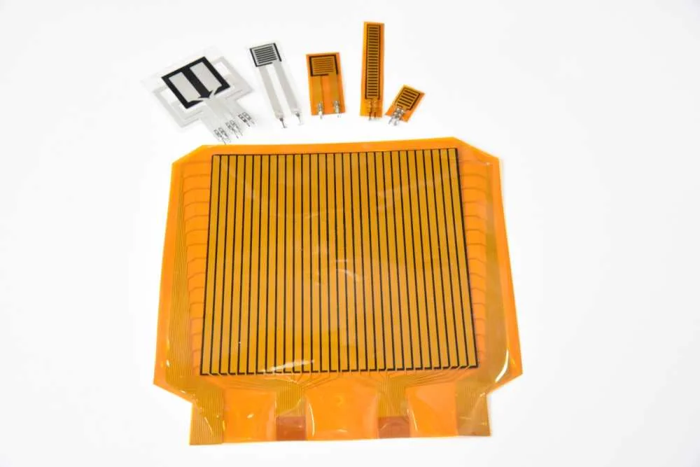
Select the sensor array first because it defines what part of the interface can be measured and at what spatial detail. Area, shape, pressure range, pitch, thickness, flexibility, temperature, test duration and cable routing all affect the choice. No single array covers every application, and the selected array must be matched with a compatible reader and software workflow.
Sensing area, geometry, range, spatial detail, loading method, temperature and expected reuse all affect the selection.
Flat, curved, narrow, annular or interrupted contact areas require different active layouts.
Overall uniformity, local peaks, contact footprint and transient events demand different detail and acquisition paths.
Temperature, duration, routing, surface condition and fixture constraints must be reviewed before quotation.
| Selection factor | Why it matters | What to provide |
|---|---|---|
| Sensing area and overall dimensions | Define coverage and physical fit | Contact drawing and available space |
| Pressure range | Sets the application-specific measurement window | Expected minimum, maximum and preload |
| Shape and surface geometry | Controls active layout and placement | Flat, curved, annular or interrupted regions |
| Spatial resolution and pitch | Influence observable contact detail | Smallest relevant feature and full coverage need |
| Static or dynamic event | Links array choice to acquisition timing | Loading sequence and rate of change |
| Selection factor | Why it matters | What to provide |
|---|---|---|
| Rows, columns and sensing points | Describe the matrix structure | Features or regions that must be distinguished |
| Thickness and flexibility | Affect fit and interface disturbance | Gap, curvature and allowable intrusion |
| Temperature and environment | May limit the sensor and connection path | Operating condition and exposure |
| Test duration and cable routing | Shape placement, protection and reader location | Duration, access and tail path |
| Calibration requirements | Define how results will be interpreted | Comparison goal, units and reporting need |
Published examples below stay bound to representative configurations. They are not universal specifications.
For repeatable distribution and contact-pattern checks across common engineering fixtures.
One matched system configuration uses a 44 × 52 matrix with 2,288 sensing points and 100 Hz acquisition.
Sensing area, shape, range, density and connection arrangement.
Geometry, pressure range, required detail, duration, temperature, surface condition, reuse and reader compatibility.
For interfaces where smaller pressure features and more detailed distribution images are required.
One matched system configuration uses a 128 × 128 matrix with 16,384 sensing points and 100 Hz acquisition.
Array geometry, active area, density and compatible wired or wireless acquisition.
Actual pitch, sensing area, range, temperature, scan rate, output and calibration approach.
For footprints that extend beyond a compact array, including larger pads, fixtures and contact surfaces.
A large-area configuration is available with a 50 Hz acquisition path; the complete matrix and active dimensions remain configuration-specific.
Area, aspect ratio, connection layout, density and multi-unit arrangements.
Coverage, seams or gaps, routing, loading uniformity, range, scan rate and compatible reader capacity.
For applications where small contact changes must be observed without treating a general sensor range as sufficient.
One integrated reference configuration uses a 32 × 128 matrix with 4,096 sensing points and 50 Hz wireless acquisition.
Active area, geometry, range and matched acquisition arrangement.
Expected minimum and maximum pressure, preload, surface compliance, drift, duration and calibration conditions.
For interfaces where a standard rectangular layout cannot reach or isolate the measurement region.
Custom evaluation can address size, shape, range, density, sensing-point location and functional openings.
Outline, active layout, tail routing, connector position and matched system configuration.
Drawing, tolerances, active and excluded zones, expected volume, fixture, range and validation method.
Available specifications depend on the selected sensor, data acquisition hardware and software configuration. Final parameters will be confirmed for the application before quotation.
Sensor array placement depends on the contact interface. Geometry, active sensing area and flat-tail routing affect selection; final reader and software compatibility must be confirmed. These neutral diagrams are not fixed product models.
Use the real footprint to define coverage before choosing pressure range and spatial detail.
Sensor→Reader→Output
Flexibility alone is not enough; active-area shape, installation method and cable clearance must fit the curvature.
Sensor→Reader→Output
The selected layer, insertion gap and fixture can change both sensor protection and interpretation of the pressure map.
Sensor→Reader→Output
A slim active area can isolate the contact strip, but pitch, alignment and routing must suit the usable width.
Sensor→Reader→Output
An irregular outline can be evaluated around usable and excluded zones, but geometry and system compatibility remain project-specific.
Sensor→Reader→Output
One sensor array cannot cover every measurement scenario. Final sensor geometry, sensing area, reader and software configuration will be confirmed for the application before quotation.
A sensor cannot be selected independently of matrix capacity, connection, scan rate, software functions and the physical test setup.
Review data acquisitionRouting, surface preparation and loading practice affect both the sensor and the data.
Remove debris and review edges, gaps and surface texture that could concentrate load or damage the array.
Align the active area, protect the tail and avoid folds, sharp creases or uncontrolled shear during loading.
Record fixture, loading sequence, orientation, reuse and calibration conditions so measurements can be interpreted consistently.
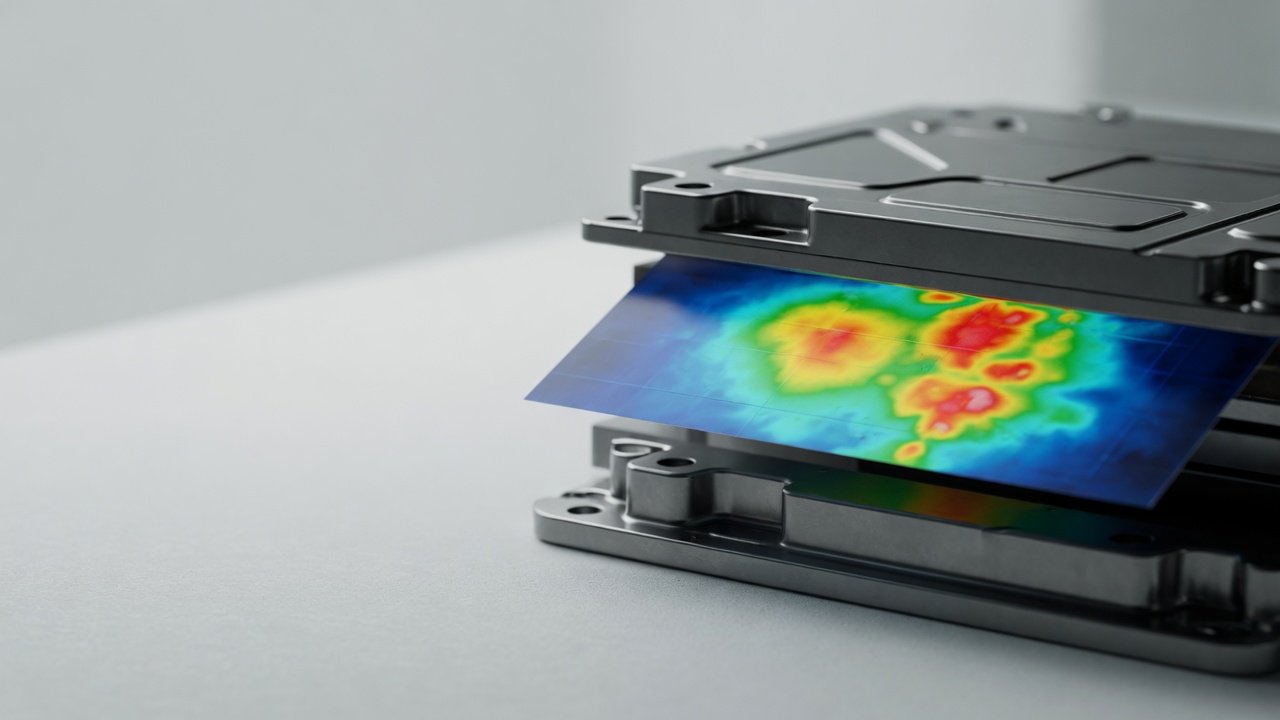
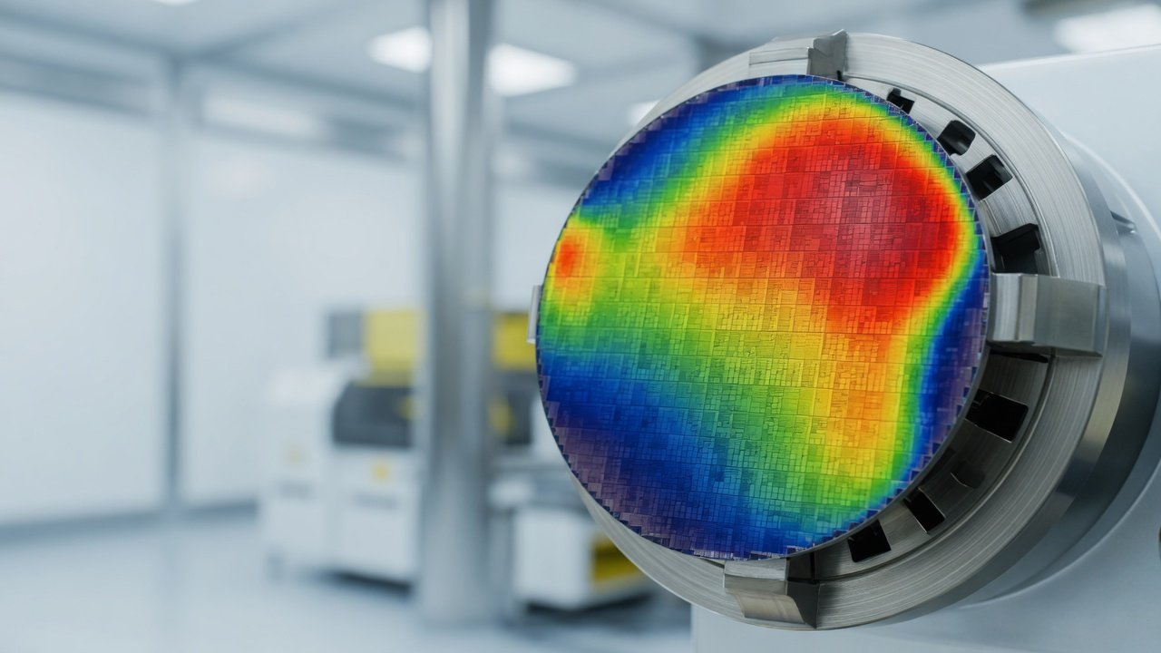
Selection begins with the interface geometry, sensing area, expected pressure range, required spatial detail, environment and compatible acquisition hardware.
Custom shape, size, range, density, sensing layout and openings may be evaluated for qualified applications.
No. Matrix format, connection, scan-rate target and signal characteristics must be matched to compatible acquisition hardware and software.
Send the contact geometry, sensing area, expected range, fixture and measurement objective for application review.
Review application evaluation