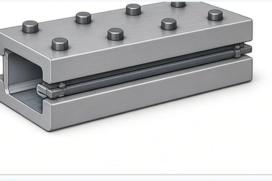
Gaskets and seals
Review contact continuity and localized high or low regions around a defined sealing interface.
Plan pressure-distribution measurements for sealing, clamping, joining, pressing and mating interfaces. A suitable setup may help teams compare contact patterns across defined process or design conditions.
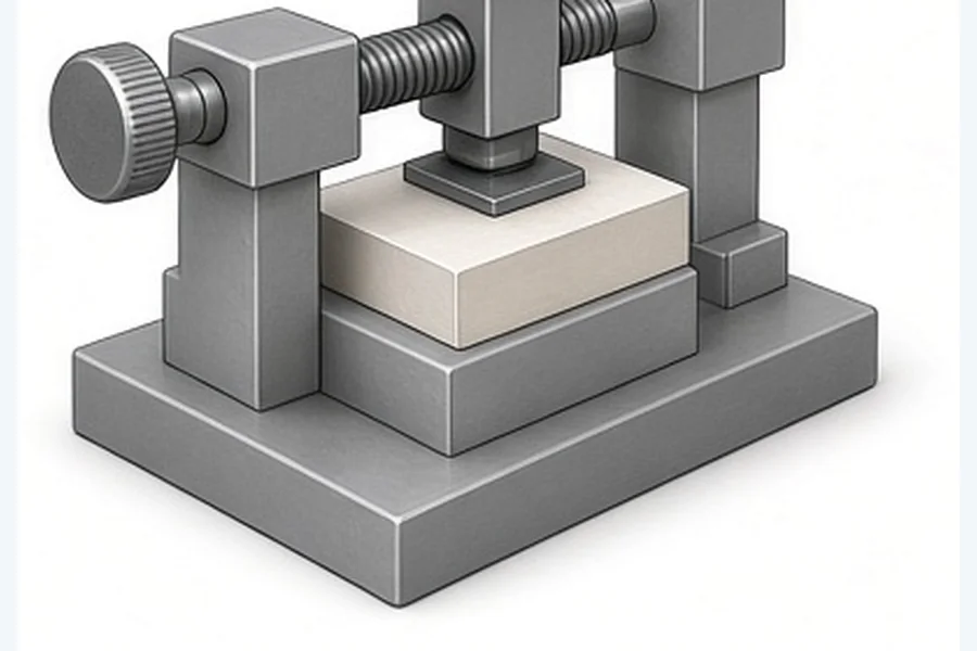
Manufacturing pressure mapping shows where a defined assembly or process interface carries contact load. It can support controlled comparison of gaskets, clamps, bolted joints, roller nips, pressing, lamination and mating surfaces by revealing localized distribution patterns. The result does not certify sealing or process quality; geometry, loading, timing and the comparison objective must be documented.
A single force value does not show where a mating interface carries load. A pressure map may help teams review local high and low regions under a defined assembly condition.
Each context requires review of geometry, loading, access and the decision the measurement should support.
Review contact continuity and localized high or low regions around a defined sealing interface.
Compare how a defined tightening or clamping condition distributes contact across the joint.
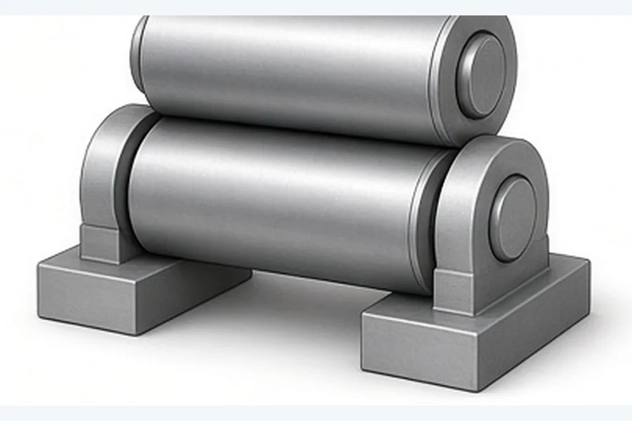
Visualize a contact band or compare roller alignment under a defined static or controlled test condition.
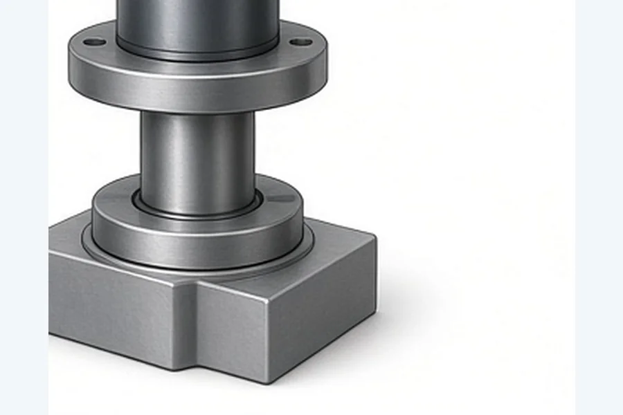
Compare how load is distributed across a layup or pressed interface during a defined test step.
Review contact distribution during a defined bonding or cure setup while process suitability remains subject to application review.
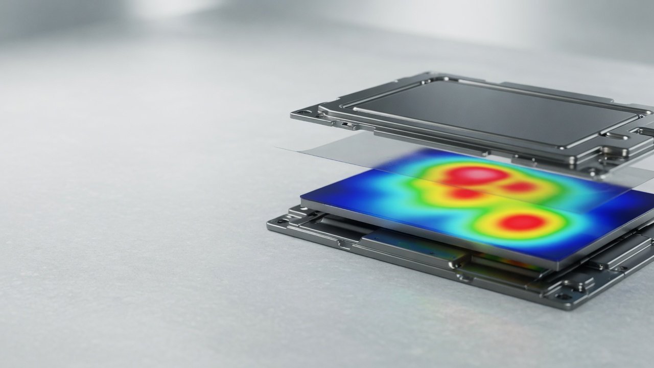
Compare contact patterns between mating parts, fixture versions or assembly iterations under documented conditions.
Selection starts with the assembly interface and the result the team needs to review.
Describe the mating surfaces, contact area, curvature, gaps and sensor access.
State how the assembly is clamped, bolted, pressed, rolled or otherwise loaded.
Identify the process or design variable and the conditions that should remain consistent.
Clarify whether the team needs a visual map, iteration comparison, exported data or reporting.
The measurement method and available outputs depend on the selected configuration.
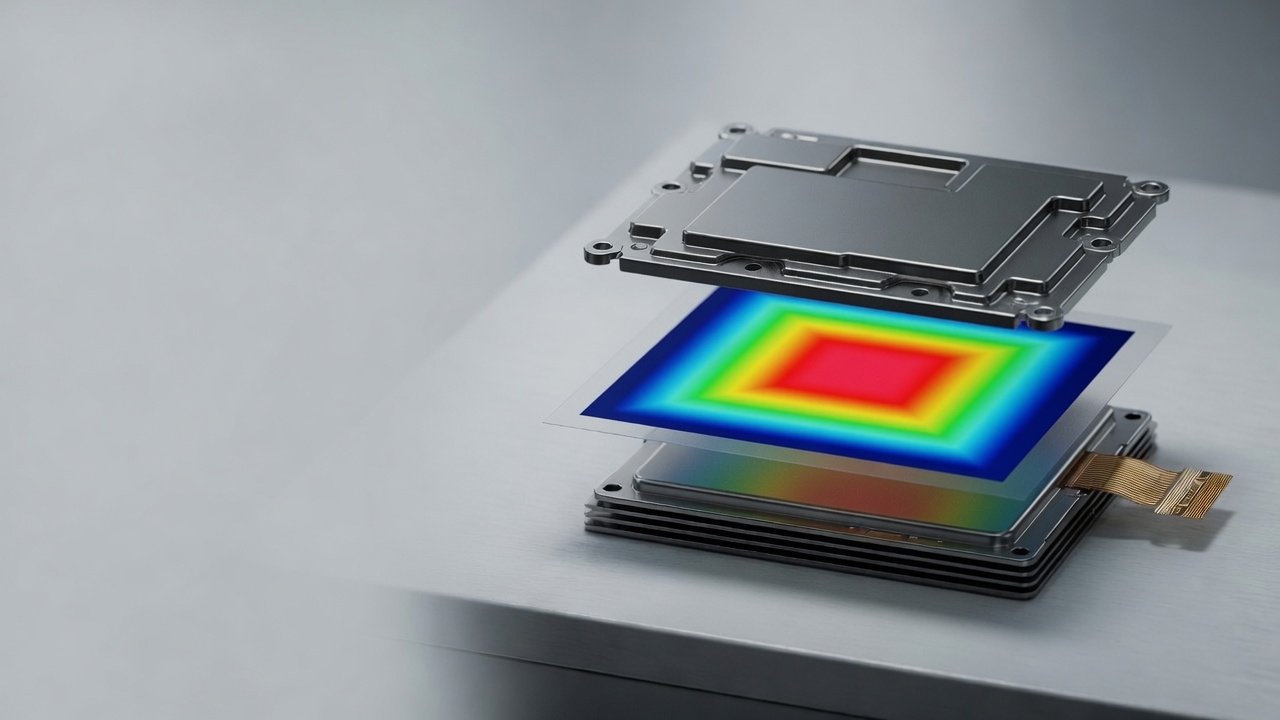
Confirm the contact area, access and practical effect of placing a sensing element at the interface.
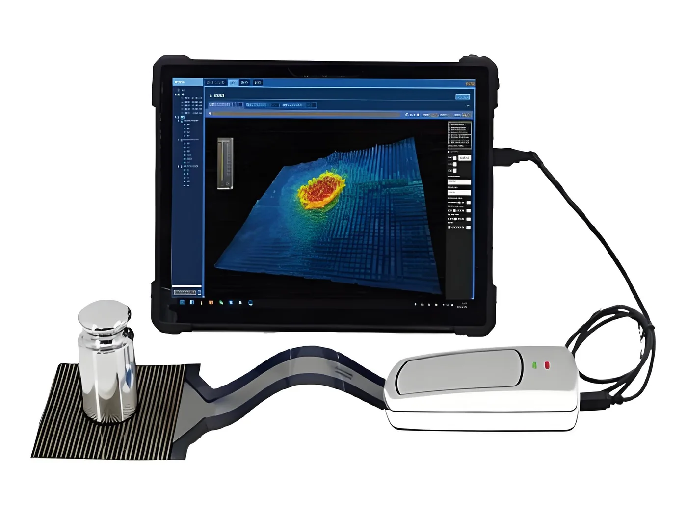
Document the assembly load, fixture setting or process condition to be compared.
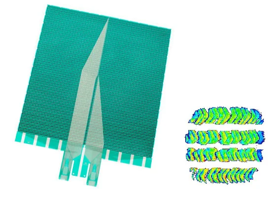
Apply the defined condition and review the contact pattern for the area of interest.
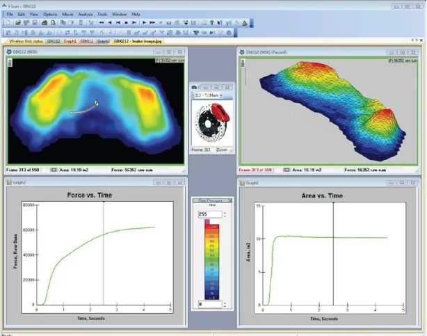
Review changes between process, fixture or design versions and prepare the required output.
Geometry, loading, sensing area, spatial resolution and reporting needs should be reviewed together.
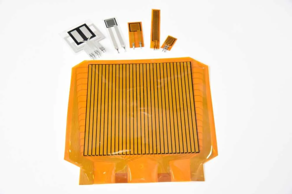
Review the current measurement-chain overview on the Products page and share the assembly constraints for configuration review.
It may support review where contact distribution matters, such as gaskets, clamps, bolted joints, pressing, lamination, roller contact, bonding and mating surfaces. Suitability depends on the interface and selected setup.
A defined measurement method can help teams compare contact patterns between fixture settings, assembly approaches or design iterations. Test conditions should be controlled and documented for a useful comparison.
Share the mating surfaces, contact area, loading method, expected operating context, access constraints and the result the team needs to compare or document.
No. Available views, export and reporting functions depend on the selected configuration and should be confirmed before quotation.
Use the published overview pages to review the measurement chain and prepare useful application details.
Share the mating surfaces, loading method, constraints and comparison your team needs to make. PressMapper can help frame a configuration for application review.
Review application evaluationPrefer email? Reach us at info@pressmapper.com